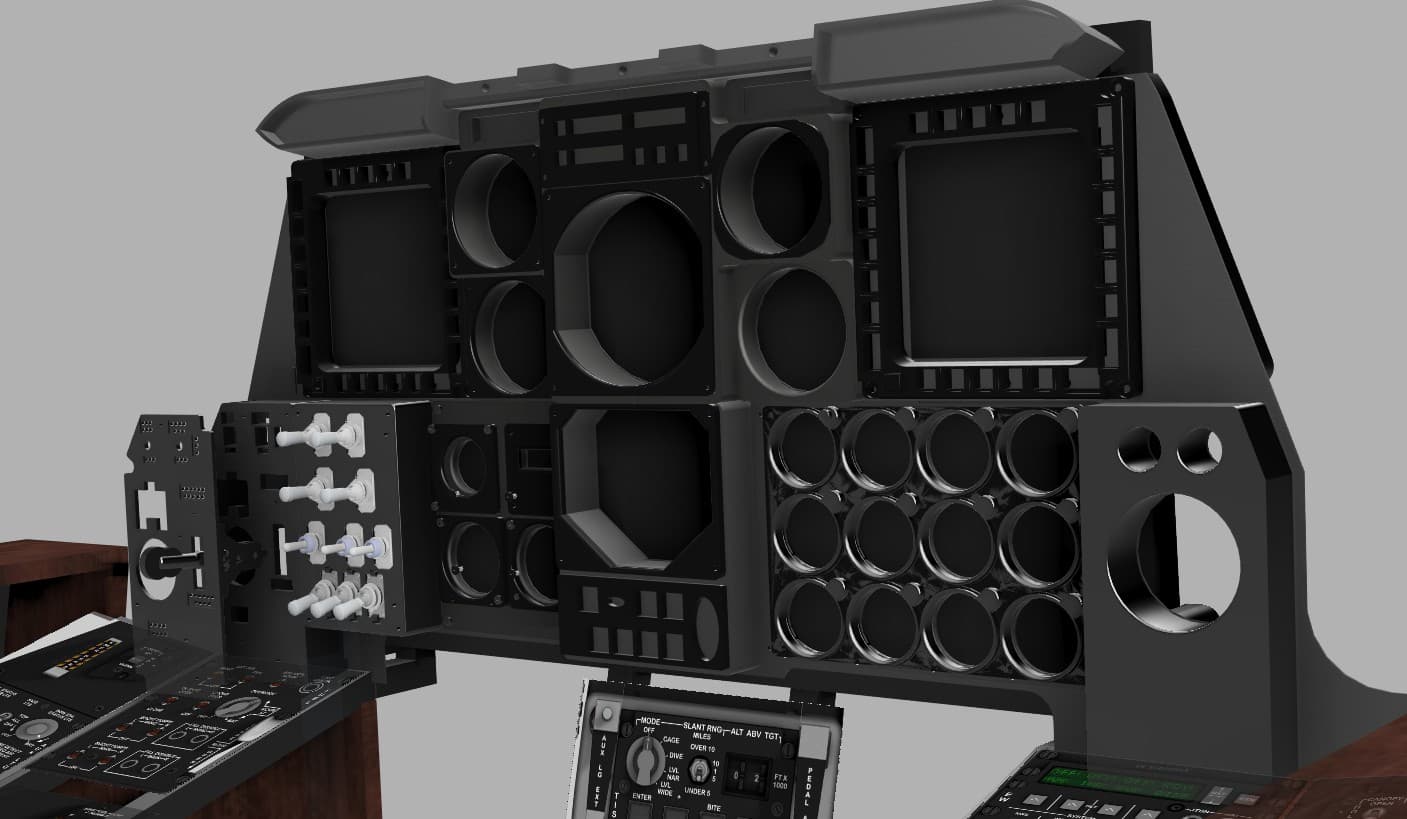
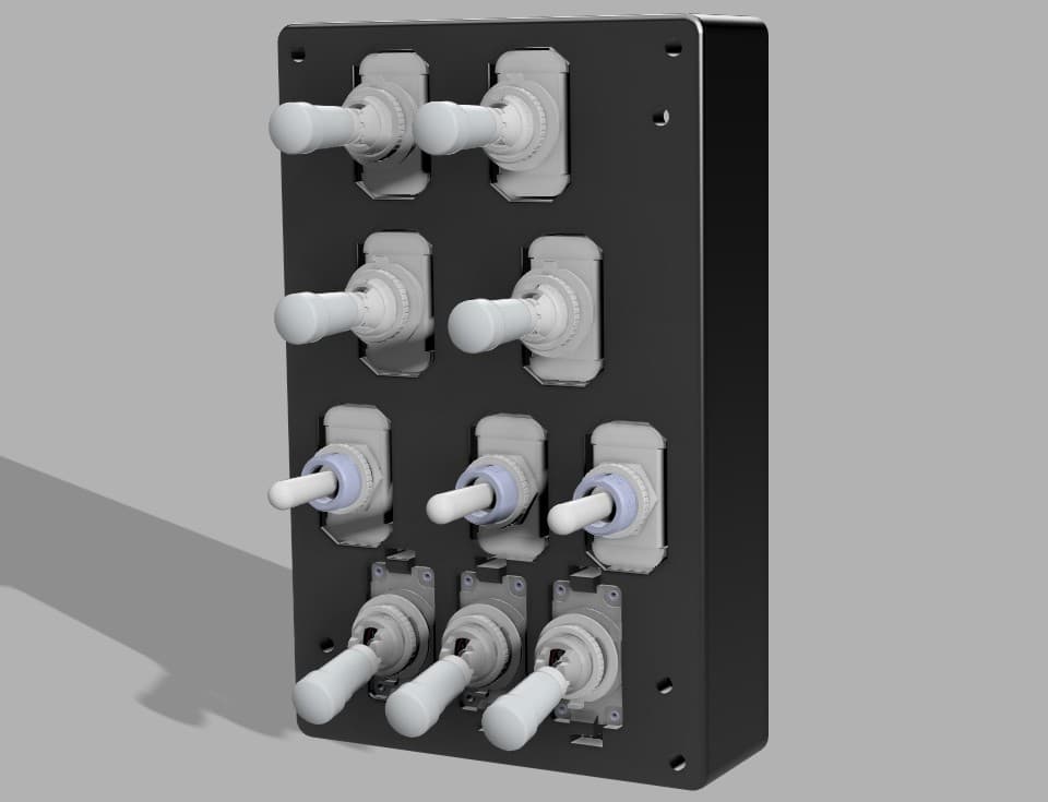
Fairchild Republic A-10 Thunderbolt II
The Fairchild Republic A-10 Thunderbolt II, also widely known by the nickname A-10 Warthog, is a single-seat, twin-turbofan, straight-wing, subsonic attack aircraft developed by Fairchild Republic for the United States Air Force (USAF). In service since 1977, it is named after the Republic P-47 Thunderbolt strike-fighter of World War II, but is instead commonly referred to as the "Warthog" (sometimes simply "Hog").[3] The A-10 was designed to provide close air support (CAS) to ground troops by attacking enemy armored vehicles, tanks, and other ground forces; it is the only production-built aircraft designed solely for CAS to have served with the U.S. Air Force.[4] Its secondary mission is to direct other aircraft in attacks on ground targets, a role called forward air controller (FAC)-airborne; aircraft used primarily in this role are designated OA-10.
Overall Progress
32%Featured Panels
Panels

Emergency Brake & Seat Height Adjustment Panel
Location Front section of the left console, immediately beside the pilot’s seat. Purpose Provides emergency braking capability in case of hydraulic failure and allows the pilot to adjust the seat position vertically for visibility and comfort. Controls EMER BRAKE Handle — Mechanical lever; spring-loaded; yellow/black hazard stripe; used to manually apply brakes when hydraulic pressure is lost. SEAT UP / HOLD / DOWN Switch — Three-position momentary rocker; controls electric seat height adjustment. “UP” raises the seat, “DOWN” lowers it, and “HOLD” maintains position. Recommended hardware Emergency Brake Lever: Custom 3D-printed handle, 8 mm steel or brass shaft, potentiometer or hall sensor (0–5 V analog input) for position sensing. Seat Switch: ON-OFF-ON momentary toggle or spring-loaded rocker (MTS-223 or equivalent). Optional tactile feedback spring for realistic resistance. Construction Single acrylic faceplate (3 mm) mounted to the left console frame. Lever bracket behind panel includes potentiometer mount and return spring anchor. Optional laser-engraved hazard decal (black/yellow) applied over lever slot. Lighting No integrated backlighting in the real A-10C; optional indirect cockpit floodlight illumination may be simulated with a low-intensity LED.

Flight Control Emergency Override Panel
Panel name Flight Control & Emergency Override Panel Location Left console, below the Autopilot and LASTE panel. Purpose Provides manual control and emergency override functions for the aircraft’s primary flight control systems. It allows the pilot to disengage hydraulic control servos, operate trim in emergency mode, and revert to manual (mechanical) flight control if both hydraulic systems fail. Controls SPD BK EMER RETR Switch — Two-position toggle switch to retract speed brakes in an emergency (momentary ON). PITCH/ROLL TRIM Switch (NORM / EMER OVERRIDE) — Two-position toggle; enables emergency trim system bypassing the normal electrical circuit. NOSE ON Control (Trim Hat) — Four-way hat switch allowing manual trim adjustment: Nose Up / Nose Down / Left Wing Down / Right Wing Down. AILERON EMER DISENGAGE Switches (L / R) — Two guarded two-position toggles to disengage the left and right aileron hydraulic actuators. ELEVATOR EMER DISENGAGE Switches (L / R) — Two guarded two-position toggles to disengage the left and right elevator hydraulic actuators. FLAP EMER RETR Switch — Two-position toggle to retract flaps in case of hydraulic failure. FLT CONT Switch (NORM / MAN REVERSION) — Two-position rotary selector; enables manual reversion mode, connecting flight controls directly to control cables bypassing hydraulics. Recommended hardware Toggles: 1 × ON-OFF momentary for SPD BK EMER RETR 1 × ON-ON for PITCH/ROLL TRIM NORM/EMER 4 × ON-OFF (guarded) for AILERON and ELEVATOR EMER DISENGAGE 1 × ON-OFF for FLAP EMER RETR Trim Hat: 1 × 4-way momentary hat switch (with common ground) Rotary Selector: 1 × 2-position rotary or toggle with distinctive orange cap for FLT CONT Construction 3 mm matte black acrylic faceplate with engraved white legends and yellow/black caution border. Use M3 hardware for mounting; toggles spaced at least 15 mm center-to-center. “MAN REVERSION” knob recommended in brown or orange for visual realism. Lighting Green LED backlighting behind legends. Optional amber LED highlighting the border to accent emergency use.

Fuel Control Panel
Location Upper left console, directly behind the Emergency Brake and Seat Adjustment panel. Purpose Manages the aircraft’s entire fuel system — including internal and external tanks, cross-feed, refueling, and boost pumps — to ensure balanced fuel distribution and engine feed during all flight conditions. Controls EXT TKS (WING / FUS) — Two 2-position toggles controlling the external wing and fuselage tanks (ON/OFF). SIG AMPL (NORM / OVERRIDE) — Rotary selector to switch signal amplification for fuel system sensors and indicators. LINE CHECK Button — Momentary pushbutton used to verify fuel line integrity and flow test. TK GATE (OPEN / CLOSE) — Controls the fuel transfer gate between tanks. CROSS FEED (OFF / ON) — Enables fuel cross-feed between left and right engines. BOOST PUMPS (WING-L/R & MAIN-L/R) — Four individual toggle switches activating the left and right boost pumps in each tank group. FILL DISABLE (WING-L/R & MAIN-L/R) — Four toggles preventing unwanted refueling or transfer from specific tanks. RCVR LT Switch — Controls the fuel receptacle light for night refueling visibility. FUEL HANDLE (OPEN / CLOSE) — Mechanical lever that opens or closes the aerial refueling receptacle. Recommended hardware Toggles: 8 × 2-position maintained (ON-OFF) MTS-102 or aviation-style SPST switches. Rotary selector: 1 × 3-position (OFF / BAT / RCVR LT) rotary or ON-OFF-ON toggle. Pushbutton: 1 × momentary (normally open) illuminated type for Line Check. Lever: 1 × custom 3D-printed handle with micro switch or Hall sensor for OPEN/CLOSE detection. Construction Dual-layer acrylic panel (3 mm faceplate + 5 mm sub-layer) with engraved white text and guarded toggle holes. Optional rotary guard ring for “SIG AMPL” and lever slot cut with 1 mm tolerance. Labeling consistent with MIL-STD cockpit engraving (white on black). Lighting Internal green LED backlight (520 nm) behind engraved legends. RCVR LT switch may be simulated using a separate warm-white LED circuit.

IFF (Identification Friend or Foe) Control Panel
Location Left console, below the Yaw & Pitch SAS / Takeoff Trim Panel. Purpose Allows the pilot to manage the IFF transponder system, ensuring secure identification of the aircraft to friendly radar systems. Provides control over transmission modes, encryption, testing, and audio monitoring. Controls CODE Selector (ZERO / B / A / HOLD) — Four-position rotary switch used to select encryption codes or zeroize (erase) all IFF crypto data. REPLY Indicator (Green) — Illuminated light indicating a valid IFF response transmission. TEST Indicator (Green) — Illuminated light confirming system self-test status. MASTER Switch (OFF / STBY / NORM / EMER) — Four-position rotary selector for IFF transponder operational mode: OFF: System disabled. STBY: Power applied but no transmission. NORM: Standard IFF operation. EMER: Emergency squawk for distress identification. AUDIO OUT Jack — Allows headset monitoring of IFF signal tones. LIGHT Switch (ON / OFF) — Enables or disables panel lighting. MODE Selector Knobs (1, 2, 3/A, C) — Four two-position toggle switches controlling specific IFF modes used for various interrogations. MODE 3/A Code Wheels (Four-digit) — Rotating thumb wheels used to set Mode 3/A identification code (0000–7777). RAD TEST Button — Momentary pushbutton to initiate radio signal test. IDENT Button — Momentary pushbutton that forces an identification pulse reply to friendly radar systems. MIC Jack — Allows connection to aircraft comm system for direct voice identification or IFF audio monitoring. Recommended hardware Rotary switches: 1 × 4-position for CODE selector. 1 × 4-position for MASTER mode. Toggles: 4 × 2-position ON-OFF for Modes 1, 2, 3/A, and C. Pushbuttons: 2 × momentary (normally open) for RAD TEST and IDENT. Indicators: 2 × 5 mm green LEDs (REPLY, TEST). Rotary encoders or thumbwheel switches: 4 × digit wheels or 4 rotary encoders for Mode 3/A code. Construction 3 mm engraved black acrylic faceplate with white legends. Optional secondary mounting plate for encoders and LEDs. Ensure uniform spacing for toggle rows (min. 12 mm). Lighting Green backlight for labels and legends, with separate illumination for REPLY/TEST indicators. Optional diffused LED under the MODE 3/A section for clarity. Notes The IFF panel replicates the AN/APX-113 system used in the A-10C. For DCS-BIOS implementation, each mode toggle and rotary selector corresponds to discrete commands in the IFF device section. The ZERO function can be mapped as a protected command to prevent accidental activation.

IFF/SAT Antenna & EGI HQ-TOD Select Panel
Location Left console, below the Intercom panel and just above the KY-58/secure comms area. Purpose Routes antennas and time-of-day synchronization for radios: selects which IFF antenna is used, chooses SATCOM antenna gain, and tells the EGI which radio (ARC-210 or ARC-164) provides Have Quick (HQ) Time-Of-Day. Controls IFF ANT UPPER / BOTH / LOWER — 3-position selector for the IFF transponder antenna routing. SAT ANT HIGH / LOW — 2-position toggle selecting SATCOM antenna gain. EGI HQ TOD: ARC-210 / OFF / ARC-164 — 3-position selector that assigns the radio used for HQ TOD (or disables it). Recommended hardware (simpit) IFF ANT: 1 × 3-position switch (use ON-ON-ON toggle or a 3-pos rotary). SAT ANT: 1 × 2-position ON-ON toggle. EGI HQ TOD: 1 × 3-position switch (ON-OFF-ON works well in DCS-BIOS for three discrete states). Construction 3 mm matte-black acrylic faceplate with engraved legends. Center-to-center spacing ~18 mm between toggles; use miniature toggles to match the compact real panel. Lighting Green backlight behind legends (shared light rail with adjacent comms panels). Notes (DCS-BIOS) Map each switch to its discrete control. For 3-position toggles with a floating middle (OFF), define two inputs (up/down) or use an ON-OFF-ON wired to two separate pins so each extreme is readable at startup. Add 0.1 µF caps or software debounce if needed.

Intercom Control Panel (INTER)
Location Left console, lower section — beneath the UHF Radio Control Panel and adjacent to the IFF Mode Select Panel. Purpose Manages internal and external communication channels, allowing the pilot to select and adjust audio sources such as intercom, radios, navigation aids, and datalinks. It also controls headset volume and provides a CALL function for crew communication. Controls INT, AIM, FM, IFF, VHF, UHF, ILS, TCN, HM Selector Knobs (8 total) — Individual rotary volume controls for each communication or navigation channel: INT: Internal intercom system (crew/headset) AIM: Airborne Intercept Missile tone audio FM / VHF / UHF: Radio channels IFF: Identification Friend or Foe audio ILS: Instrument Landing System tones TCN: TACAN navigation tone HM: Homing beacon tone MASTER Volume Knob (VOL) — Main audio level control for all channels. MODE Selector Knob (INT / VHF / FM / HF) — Selects the primary transmit mode (intercom, VHF, FM, or HF). CALL Button — Momentary pushbutton that activates the intercom call function for ground crew or internal communication. Recommended hardware Rotary potentiometers: 8 × 10 kΩ linear pots (individual channel volumes) 1 × 10 kΩ for MASTER volume Rotary switch: 1 × 4-position selector (INT / VHF / FM / HF) Pushbutton: 1 × momentary pushbutton (CALL) Construction 3 mm matte black acrylic faceplate, engraved white text. Volume knobs 12–15 mm; spacing 15–18 mm for accessibility. “INTER” engraved vertically on both edges for labeling consistency with cockpit layout. Lighting Green LED backlighting for all text and scale marks. Optional back-illumination behind knob markings for premium realism. Notes This panel interfaces directly with the A-10C’s Audio Management System, controlling which radio or navigation source is active and how audio is routed to the pilot’s headset. In DCS-BIOS, most functions can be simulated using analog inputs for potentiometers, with digital mapping for the CALL button and mode selector. When wiring multiple potentiometers to shift-register expanders, ensure proper ground isolation and decoupling capacitors (0.1 µF) to minimize analog noise.

KY-58 Secure Voice Control Unit (RCU)
Location Left console, immediately below the VHF FM radio and adjacent to the antenna select and intercom panels. Purpose Controls the KY-58 Secure Voice encryption system, which provides secure (encrypted) voice communication capability over UHF, VHF, and HF radios. The panel allows the pilot to enable or disable encryption, select operation mode, manage encryption keys, and perform zeroization (erasing all crypto keys in emergencies). Controls ZEROIZE Lever (Guarded, Red) — Destroys all loaded encryption keys immediately when lifted and activated. Used in emergency situations to prevent compromise. PLAIN / C/RAD 1 / C/RAD 2 Selector — Sets transmission mode: PLAIN: Unencrypted (normal comms). C/RAD 1 / 2: Ciphered radio channel 1 or 2 (secure mode). MODE Selector (OP / LD / RV) — Sets KY-58 operating mode: OP: Normal operation. LD: Load mode (for key entry or data transfer). RV: Receive mode (for loading keys from an external source). DELAY Switch (1–6) — Six-position selector for delay timing, used in synchronization during key loading or radio operations. FILL Knob (1–6) — Rotary selector for key channel slot. Each slot stores a separate encryption key. POWER Switch (ON / P / R / OFF) — Controls system power and function: ON: Activates the unit. P: Plain (bypass encryption). R: Receive mode only. OFF: Power off. Recommended hardware (simpit) ZEROIZE: 1 × guarded toggle (ON) with red safety cover. MODE and PLAIN/C-RAD: 3-position rotary switches. DELAY and FILL: 6-position rotary switches (12-step type preferred for feel). POWER: 4-position rotary switch. Construction 3 mm matte-black acrylic faceplate with white engraved legends; ZEROIZE lever area painted red with white text. Optional backlighting via green LED strip under panel edge. Knob spacing and sizes consistent with Collins-style avionics panels. Lighting Subdued green backlighting (shared with left console lighting bus). ZEROIZE lever may have an independent red LED indicator for realism. Notes (DCS-BIOS) This panel is not yet functional in the base DCS A-10C module (KY-58 functions are not simulated). However, it can be implemented for realism with custom Arduino input mapping and lighting logic. You may assign toggle inputs to dummy DCS-BIOS functions or use them for general cockpit interactivity (e.g., power sequencing simulation).

Signal Lights & Fire Detection / HARS-SAS Override Panel
Location Left console, directly behind the Fuel Control Panel. Purpose Controls auxiliary cockpit lighting, performs system lamp and fire detection tests, and provides manual override control for the Heading and Attitude Reference System (HARS) and Stability Augmentation System (SAS). Controls REFUEL STATUS & INDEXER LTS (DIM–BRT) — Rotary potentiometer controlling brightness of refueling status and indexer lights. WPN STA STATUS LTS (DIM–BRT) — Rotary potentiometer controlling brightness of weapon station status lights. TOP / ALL / OFF Selector — Three-position rotary switch selecting which lights to test (TOP only, ALL lamps, or OFF). SIGNAL LIGHTS LAMP TEST Button — Momentary pushbutton used to initiate lamp test for all cockpit indicators. FIRE DETECT / BLEED AIR LEAK TEST Button — Momentary pushbutton used to simulate overheat and fire conditions to test warning lights and sensors. HARS/SAS Override (OVERRIDE–NORM) — Two-position toggle switch used to manually bypass or restore the HARS/SAS automatic control circuits. Recommended hardware Rotary knobs: 2 × 10 kΩ linear potentiometers (for DIM–BRT control). Selector: 1 × 3-position rotary switch (OFF–TOP–ALL). Pushbuttons: 2 × momentary (normally open) pushbuttons, ideally backlit. Toggle: 1 × ON-OFF maintained toggle for HARS/SAS override. Construction Single 3 mm black acrylic faceplate with engraved white legends. Backplate optional for LED diffusion and wiring stability. HARS/SAS toggle should be metal-guarded for authenticity. Lighting Sub-panel backlight using green (520 nm) LEDs for DIM–BRT adjustment controls. Optional integration of warm-white LEDs behind test buttons for visibility.

Stall Warning & Peak Performance Adjustment Panel
Location Lower section of the left console, just above the Anti-G and oxygen system area. Purpose Provides audio volume adjustment for stall warning tone and calibration of the peak performance indicator system, which assists the pilot in maintaining optimum aircraft performance under high angle-of-attack conditions. Controls STALL VOL Knob — Adjusts the volume of the stall warning tone heard in the pilot’s headset. Turning clockwise increases the warning tone intensity. PEAK PRFM Knob — Used by maintenance crews or pilots to calibrate or fine-tune the peak performance (AOA) system. Normally left in its preset detent during flight. Recommended hardware (simpit) 2 × 10 kΩ rotary potentiometers with push-fit tactile knobs. Optional shared encoder for fine digital calibration if connected to analog input (0–5 V). Knobs: 12–15 mm diameter, flat-topped military gray style to match console aesthetic. Construction 3 mm black matte acrylic faceplate with engraved white legends. Standard 18 mm spacing between knob centers. Mount directly above left-console side panels for ease of wiring to the main audio bus. Lighting Indirect illumination from console floodlights only (no dedicated backlighting). Notes (DCS-BIOS) Not implemented in the base DCS A-10C module, but can be simulated using analog potentiometers mapped to sound or warning light intensity in external cockpit controllers. For immersive setups, map STALL VOL to a sound output gain channel and PEAK PRFM to an analog trim or placeholder function.

UHF Radio Control Panel (AN/ARC-164)
Location Left console, lower mid-section — directly beneath the VHF/UHF (ARC-210) radio control panel. Purpose Provides manual and preset frequency control for UHF communication, allowing secure voice communication between aircraft and ground control. The pilot can switch channels, test display functions, set guard frequencies, and adjust volume or squelch. Controls Frequency Display (Green LED) — Indicates active operating frequency or channel information (e.g., 277.625 MHz). Channel Display (Green LED) — Displays the selected channel number (1–20). TEST DISPLAY Button — Momentary pushbutton that activates the display test function, illuminating all digits and indicators. STATUS Indicator — Displays UHF radio operational status (e.g., ON, FAIL). MODE Selector (A / M / 1 / 2 / 3) — Rotary selector for preset group selection or channel bank. MAIN / BOTH / ADF Selector — Rotary switch: OFF: Power off MAIN: Primary radio only BOTH: Transmit/receive both main and guard frequencies ADF: Enables Automatic Direction Finder mode for navigation PRESENT / MNL / GRD Selector — Rotary switch: PRESENT: Uses selected channel preset MNL: Manual frequency tuning GRD: Guards emergency frequency (243 MHz) TONE Switch (T / OFF) — Enables sidetone during transmission for headset feedback. SQUELCH Switch (ON / OFF) — Toggles audio squelch circuit to suppress static. VOLUME Knob (VOL) — Rotary potentiometer controlling audio output level. PRESET CHANNEL Selector (CHAN) — Rotary switch selecting channel 1–20 for preset frequencies. Recommended hardware Rotary switches: 3 × 4-position (MODE, MAIN/BOTH/ADF, PRESENT/MNL/GRD) 1 × 20-position or encoder for channel selection Potentiometer: 1 × 10 kΩ linear for volume control Pushbuttons: 1 × momentary (TEST DISPLAY) Toggle switches: 2 × ON-OFF (TONE, SQUELCH) Displays (optional): 2 × 7-segment LED displays or LCD for frequency/channel simulation Construction 3 mm matte black acrylic faceplate, engraved white text, green backlighting. Knobs 12–15 mm diameter for ergonomics. Position “TONE” and “SQUELCH” toggles symmetrically under the volume knob. Lighting Green LED backlighting for all engraved text. Optional amber indicator for STATUS light. Notes This panel simulates the AN/ARC-164(V) UHF radio used in the A-10C. In DCS-BIOS, frequency and channel selection can be controlled using encoder inputs for precise tuning. For realism, map PRESENT/MNL/GRD and MAIN/BOTH/ADF to dedicated rotary switches. Include hardware debouncing for the TEST button to avoid repeated trigger events.

VHF FM Radio Control Panel (COMM 2)
Location Left console, below the UHF Radio panel and adjacent to the intercom and antenna select panels. Purpose Provides control of the VHF FM communication radio, used primarily for close air support and communication with ground units. Allows the pilot to select preset or manual frequencies, adjust volume and squelch, and configure transmission modes. Controls VOL / SQDIS Knob — Dual concentric knob controlling radio volume and squelch disable. VHF / TONE Selector Switch — Enables or disables audio tone output. Frequency Selector Knobs (4 total) — Set the VHF FM frequency manually (e.g., 30.000–87.975 MHz). PRESENT Window — Displays currently active preset channel (1–20). EMER / AM / MAN / PRE / LOAD Selector — Rotary selector for operation mode: EMER: Emergency frequency (default fail-safe). AM: Amplitude modulation (rarely used). MAN: Manual frequency entry. PRE: Preset channel selection. LOAD: Used for programming presets. DF / TR / OFF Selector — Function switch: DF: Direction finding mode (if available). TR: Transmit/receive mode. OFF: Powers down radio. Recommended hardware (simpit) Dual concentric potentiometer (10 kΩ) for VOL/SQDIS. Rotary encoder or multiposition switches for frequency digits. 5-position rotary switch for MODE (EMER–LOAD). 3-position rotary for DF/TR/OFF. 7-segment display or small OLED for PRESENT channel display. Construction 3 mm matte black acrylic or painted aluminum faceplate. White engraved labels; legends illuminated by green LED backlighting. Knobs spaced 17–20 mm; main rotary selector larger (16 mm shaft knob) for realistic tactile feedback. Lighting Subsurface green LED backlight for legends and numeric windows. Edge-lighted acrylic or fiber routing optional for compact builds. Notes (DCS-BIOS) Use the VHF FM Radio module. Each rotary and switch can be mapped to its discrete functions. Preset display can be simulated using an Arduino-driven OLED or LCD module connected to DCS-BIOS. Ensure that the frequency selector encoders wrap around logically between digit positions.

VHF/UHF Radio Control Panel
Panel name VHF/UHF Radio Control Panel Location Left console, midsection — directly below the Flight Control and Emergency Override panel. Purpose Provides complete control of the aircraft’s VHF/UHF communications system (ARC-210). Used to tune frequencies, select modes, transmit, receive, and manage encryption and channel presets. Controls Display Screen — Multifunction LCD showing frequency, channel, and mode information. EMER, TOD SND, TOD RCV, GPS, RT SELECT Buttons — Soft-keys for emergency frequency, time-of-day transmission, GPS synchronization, and radio terminal selection. OFF/ON/SQL Rotary Switch — Power and squelch control; “SQL” enables squelch circuit to suppress noise. MENU / AM-FM / TIME / OFFSET / SEND / RCV Buttons — Access configuration menus, select modulation type, adjust clock and frequency offset, and control transmission and reception functions. ENTER Key — Confirms data entry for frequencies or menu items. VHF/UHF Selector Toggle — Two-position toggle to switch between VHF and UHF radio systems. ADF / TR+G / ZERO (PULL) — Rotary selector for auxiliary direction finding and guard channel settings, with pull-to-zero function for quick reset. CHG / PRST / TEST Rotary Knob — Controls channel mode: manual frequency input, preset recall, or built-in test. CHANNEL Knob — Large central encoder or potentiometer used to select frequency or preset channel. PRST / MAN / MAR / 243 Selector — Four-position rotary switch for preset mode, manual tuning, maritime channel, or guard frequency (243 MHz). ECCM MASTER Knob (121 PULL) — Enables anti-jam (Electronic Counter-Countermeasures) features; pull for secure channel. Recommended hardware Display: 1 × 4"–5" TFT or OLED screen (if simulated). Rotary selectors: 3 × 4-position rotary switches (OFF/ON/SQL, PRST/MAN/MAR/243, ECCM). Encoders: 2 × rotary encoders for CHANNEL and ADF control. Pushbuttons: 10 × momentary tactile buttons for mode and function keys. Toggle: 1 × 2-position ON-ON for VHF/UHF selection. Construction 3 mm matte black acrylic faceplate with engraved white legends. Buttons should be 6–8 mm square tactile caps; rotary spacing 18–20 mm. LCD recess depth: 2–3 mm flush to panel face. Lighting Green LED backlighting behind all engraved text. Amber LED optional behind “EMER” and “ECCM” labels for active states. Notes This panel models the ARC-210 VHF/UHF transceiver, allowing secure and non-secure voice and data communication. In DCS-BIOS, many functions are digital — the physical rotary encoders can be mapped to both frequency and preset inputs. Ensure isolation between analog encoder grounds and button rows if shift registers are used.

Yaw & Pitch SAS / Takeoff Trim Panel
Location Left console, below the Signal Lights & HARS/SAS Override panel. Purpose Controls the aircraft’s Stability Augmentation System (SAS) for yaw and pitch axes, provides trim adjustment for yaw, and allows the pilot to perform takeoff trim and monitor system function. Controls YAW SAS (L / OFF / R) — Two guarded three-position toggle switches used to engage or disengage the left and right yaw SAS channels. PITCH SAS (L / OFF / R) — Two guarded three-position toggles controlling the left and right pitch SAS channels. YAW TRIM Knob — Spring-centered rotary control for adjusting yaw trim left or right, providing fine control of rudder alignment. MONITOR TEST Selector (L / R) — Two-position rotary switch for testing SAS monitoring circuits independently for each side. TAKEOFF TRIM Button — Momentary pushbutton that returns pitch and yaw trim actuators to the neutral takeoff position. Recommended hardware Toggles: 2 × ON-OFF-ON (center-off) guarded toggle switches for Yaw and Pitch SAS. Rotary control: 1 × potentiometer or encoder (spring-centered) for Yaw Trim. Selector: 1 × ON-ON toggle or 2-position rotary for Monitor Test. Pushbutton: 1 × momentary pushbutton (illuminated optional) for T/O Trim. Construction Dual-layer panel (3 mm top + 5 mm base) for switch stability and backlighting. Engraved legends in white with “TAKEOFF TRIM” highlighted text for realism. Guarded toggles positioned with 14–16 mm clearance for covers. Lighting Integrated green LED backlight behind legends. Optional amber LED under “TAKEOFF TRIM” for functional indication when pressed. Notes The SAS system ensures stability in turbulent flight and during weapons release. When simulating via DCS-BIOS, map each SAS switch to its corresponding channel (Yaw L/R, Pitch L/R) and debounce inputs to prevent double toggles.
Latest Updates


Project Update — Rethinking Panel Design for Everyone
I paused development of the A-10C panels for a moment to focus more deeply on the electronics side of SIMSTRUCT. After all… what is a body without a soul? The front console is essentially complete — all panels are designed, printed, tested, and the fit is extremely accurate. I’m very happy with how the results are shaping up. However, with the arrival of a new batch of toggle switches, it became clear that I’ll need to revisit some parts of the design, especially the mounting geometry on the back panels. This raised an important question about the future direction of SIMSTRUCT: How can I make the A-10C cockpit files and electronics accessible to everyone, regardless of skill level or component availability? Different builders use different hardware, and even small variations in switch dimensions can become barriers to an otherwise simple build. That goes against my vision — which is to make cockpit construction achievable and enjoyable for all. Because of this, I’m now exploring a “one-size-fits-all” approach for panel design. The idea is to create mounting systems and tolerances flexible enough to support a wide range of switches and components without forcing anyone to hunt for specific hardware. And I would love to hear from the community: What challenges have you faced with panel compatibility? What ideas or suggestions do you have for universal mounting systems? Are there components you think should be prioritized for broad compatibility? Thank you all for following the project and supporting each step of this journey. Much more is coming soon — and your feedback will shape it. See you in the next update.

SIMSTRUCT – Front Console Input Board Update!
(A small pause… but for a very good reason!) Hey everyone! I took a short break from modeling the A-10C panels because I needed to lock down something even more important: the electronics heart that will power the entire front dashboard. Sometimes you have to pause the build to keep the ideas fresh — and trust me, this part was worth the pause. Today I’m sharing a sneak peek of the Front Console Input Board, the “brain” that will handle all the switches, toggles, encoders and sensors from the A-10C front panel. No more cable chaos. No more guessing pins. No more fragile protoboards. Just plug, fly, and smile. 😄 What’s working right now Fully integrated ATmega32U4 (native USB) High-density input matrix with 20 shift registers (160+ digital inputs!) Four 50-pin IDC ports for clean, organized panel wiring Built-in filtering, decoupling, and DCS-ready structure Designed from scratch specifically for the A-10C front console And best of all: It will ship with firmware pre-flashed, DCS-BIOS profiles, naming conventions, and calibration already aligned with the A-10C cockpit logic. You plug it in, connect your switches, and your sim suddenly feels alive. Next milestone I’m now beginning development of the output slave board — the board that will handle backlighting, annunciators, caution lights, and other outputs. Once both boards are complete, the entire front console becomes one clean, integrated ecosystem. What’s coming If all goes well, the full A-10C front console set (inputs + outputs + panel files + wiring guides) should be ready for testing in about one month. ✈️ And beyond… A-10C was my first love, so she had to come first But after she’s complete, I’ll be releasing plane-specific electronics for multiple aircraft. Why plane-specific? Because every aircraft deserves its own optimized, precise electronics. No improvisation. No wrestling cables. No guessing pins. Just: ✔️ Plug in your console ✔️ Load your profile ✔️ And fly. Community Support Coming Soon Over the next 2 weeks, I’ll be launching: A Patreon with supporter tiers (behind-the-scenes progress, early access files, exclusive perks) The official SIMSTRUCT website, where you can follow development and access resources, files, instructions, tutorials and more. And in about 3 weeks, I’ll open the Interest List + Pre-Order Pipeline for those who want to secure their spot for the first production run. Your feedback and support mean the world to me — and they help push this project forward faster. I will keep posting Hope you enjoy the preview! Let me know what you think!

Fusion 360 Design
The design of the entire Front Console was made modular following a calibrated photo of the cockpit. A real world dimension was obtained form one panel and applied to the photo, so by proportion all the panels aligned and became at scale with the real console. The design had to take in consideration that an LCD panel will be placed in the back to provide instrument readings via Helios, so the panel could not pass that plane. This obliged me to go slightly away from the real proportion and add some additional depth to it. ( Which it turns out looked good in my opinion and made it bulkier) To facilitate with the electronic assembly, I decided to make it in 4 layers. The first layer was the frame that attaches to the console build structure and to the back panel of the AHCP. The back panel is a 5 mm part that will house the toggle switches. Many trial and errors had to be done in order to find the appropriate tolerances to properly fit the switches in the slots. The next layer comprises of a faceplate that will house the backlighting. I made small 3 mm holes ( With appropriate tolerance) to fit in the LEDs that will shine on the next layer plate. The fourth and last layer is the acrylic decal plate where the labels are engraved (see the fab/laser section for more detail)
Support This Build
Become a member to access exclusive content and full project downloads.
Join as Supporter

