Front Console Design Process in Fusion 360
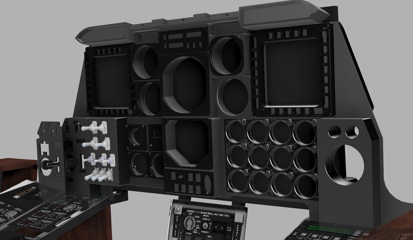
The entire front console was designed as a modular system, guided by a calibrated cockpit canvas inside Fusion 360.
To establish scale, I started with the real-world dimensions of one panel and applied that to the canvas as a reference. From there, all other panels were proportioned and aligned against it, which allowed the full console to be built at a very accurate scale relative to the real A-10 cockpit.
One important design constraint was the LCD screen that will sit behind the panels and provide instrument data through Helios. Because of that, none of the panel structures could extend beyond that plane. This forced me to move slightly away from the exact real-world proportions and add a bit more depth to the console. In the end, I think this worked well, as it gave the assembly a bulkier and more convincing look.
At the same time, I also want this cockpit to support future upgrades, including mechanical servo-driven gauges. So even at this stage, the design has to remain forward-compatible and allow those additions later with minimal refactoring.
To make electronics assembly easier, I broke the design into four layers.
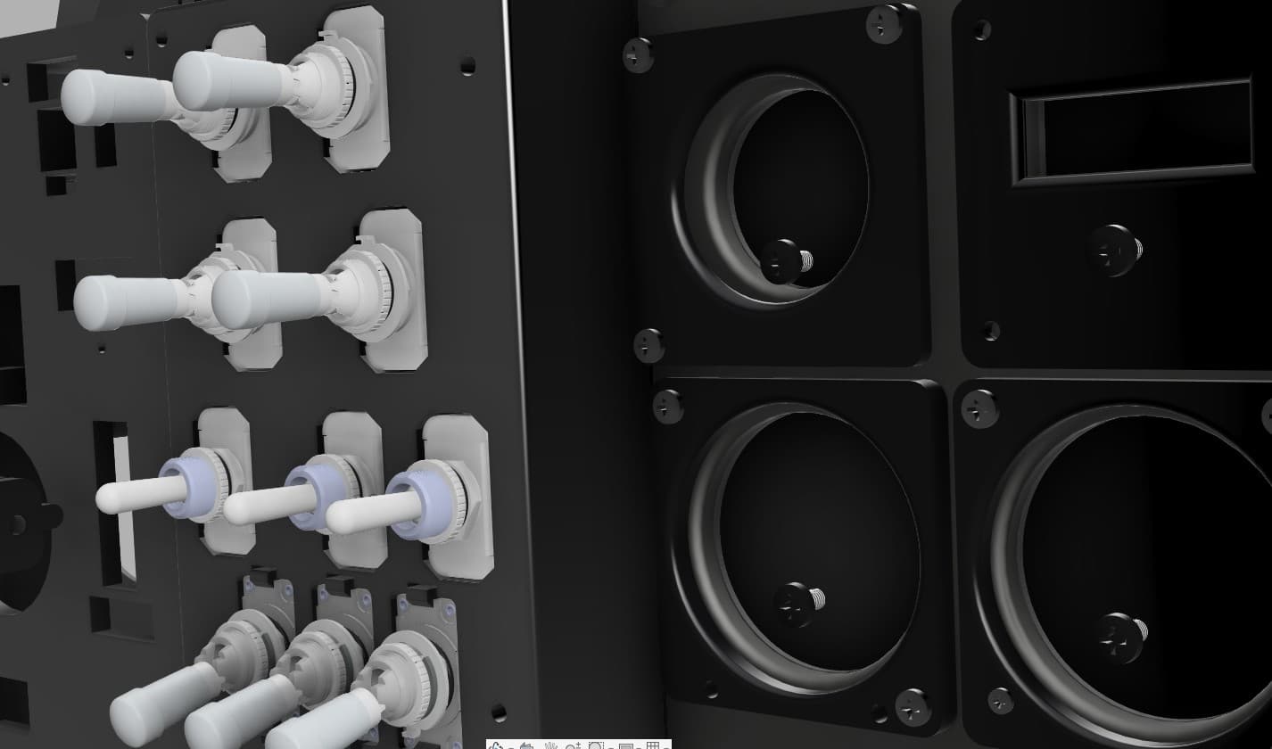
The first layer is the structural frame. This is the foundation that attaches both to the main console structure and to the rear panel assemblies, where the controls and electronics are housed.
The rear panels were designed to snugly fit the standard toggle switches selected for this build. After a fair amount of trial and error, I finally arrived at the tolerances that give a precise and reliable fit for the switches.
The next layer is the faceplate, which will carry the panel labels and the backlighting system.
This layered approach should make the console easier to assemble, easier to maintain, and much easier to upgrade as the project evolves.